


Fault Diagnosis of Flotation Cells Using Vibration and Temperature Analysis
Introduction
Flotation cells are the heart of any mineral processing plant, responsible for separating valuable minerals from gangue through the complex interaction of hydrodynamics, chemistry, and surface phenomena. These machines operate in some of the most aggressive industrial environments, continuously exposed to abrasive slurries, chemical reagents, and high mechanical loads. The impeller-stator mechanism, drive train, bearings, and motor all operate under extreme conditions that inevitably lead to wear, fatigue, and eventual failure.
Unplanned downtime of a flotation cell can be catastrophic for a processing plant. When a critical cell fails, the entire flotation circuit may need to be halted, resulting in significant production losses, increased operating costs, and potential safety hazards. Traditional reactive maintenance approaches—waiting for equipment to fail before taking action—are no longer acceptable in modern mining operations where every hour of production counts.
This is where condition-based maintenance (CBM) and predictive maintenance come into play. CBM involves ongoing monitoring of equipment conditions using an array of sensors, enabling real-time asset surveillance, trend identification, prediction of potential failures, and estimation of asset lifespan. Among the various condition monitoring techniques available, vibration analysis and temperature monitoring have emerged as two of the most powerful and cost-effective methods for diagnosing faults in flotation cells.
Vibration analysis serves as a cornerstone in condition monitoring, clarifying changes in the condition of machine components through the acquisition and analysis of vibration signals. By scrutinizing these signals, the underlying causes of mechanical changes and potential faults can be determined. Temperature monitoring, on the other hand, provides early warning of excessive friction, lubrication breakdown, and thermal stress that can lead to component failure.
This article provides a comprehensive guide to fault diagnosis of flotation cells using vibration and temperature analysis. We will explore the key mechanical components that require monitoring, the principles of vibration and temperature analysis, common fault signatures, case studies from real mining operations, and best practices for implementing a condition monitoring program.
Section 1: Understanding Flotation Cell Mechanical Components
To effectively diagnose faults, one must first understand the mechanical anatomy of a flotation cell. The following components are critical to cell operation and are primary targets for condition monitoring:
1.1 Impeller (Rotor)
The impeller is the rotating heart of the flotation cell. Its primary functions are to:
- Create hydrodynamic conditions for bubble-particle attachment
- Suspend solids in the pulp
- Disperse air into fine bubbles
- Promote mixing and circulation within the cell
The impeller operates at high speeds and is continuously exposed to abrasive slurry, making it one of the most wear-prone components in the cell. As the impeller wears, its geometry changes, reducing pumping efficiency and the ability to uniformly disperse air throughout the cell volume. Common failure modes include:
- Erosive wear of impeller blades
- Fatigue cracking
- Unbalance due to uneven wear or material buildup
- Loosening of the impeller on the shaft
1.2 Stator (Diffuser)
The stator, also known as the diffuser, surrounds the impeller and serves to:
- Convert the kinetic energy of the slurry into pressure
- Direct the flow pattern within the cell
- Enhance air dispersion
- Reduce turbulence in the cell
Like the impeller, the stator experiences significant wear from abrasive particles. Wear of the stator alters the flow pattern, reduces pumping efficiency, and can lead to sanding—the settling of heavy particles on the tank floor.
1.3 Drive Train and Bearings
The drive train transmits power from the motor to the impeller through a system of shafts, couplings, belts, and bearings. This system is subject to:
- Bearing wear: Prolonged, high-speed shaft rotation can lead to bearing failures
- Misalignment: Between the motor and the drive shaft
- Unbalance: In rotating components
- Belt tension issues: Loose or worn belts causing vibration
- Coupling wear: Resulting in backlash and impact forces
The condition monitoring of the drive train is critical because failures here are often easier to detect through vibration and temperature analysis than failures occurring inside the slurry environment.
1.4 Motor
The motor provides the power for the entire drive system. Motors are subject to:
- Bearing overheating: Often the first sign of lubrication failure
- Electrical imbalances
- Insulation breakdown
- Cooling system failure
Temperature monitoring of motor windings and bearings provides early warning of excessive friction or lubrication breakdown.
1.5 Scraper Mechanism
The scraper mechanism removes the mineral-laden froth from the cell surface. It typically consists of a motor, gearbox, and rotating scrapers. Common issues include:
- Bearing overheating (temperature rise exceeding 25°C is a warning sign)
- Vibration or oscillation of the scraper mechanism
- Inflexible rotation of the scraper mechanism shaft
- Oil leakage from the reducer
1.6 Blower (Air Supply System)
The blower supplies the air required for flotation. Monitoring of the blower includes:
- Inlet and exhaust pressure
- Bearing temperature
- Motor current changes
- Vibration and noise levels
Section 2: Fundamentals of Vibration Analysis
2.1 What is Vibration Analysis?
Vibration analysis is a technique that measures the vibration characteristics of rotating machinery to detect and diagnose faults. Every machine produces a unique vibration signature when operating normally. When a fault develops, the vibration signature changes in predictable ways. By measuring and analyzing these changes, maintenance personnel can identify the nature, severity, and location of faults before they lead to catastrophic failure.
2.2 Measurement Parameters
The key parameters measured in vibration analysis include:
| Parameter | Description | Units | Significance |
| Amplitude | The magnitude of vibration | mm/s (velocity), mm (displacement), m/s² (acceleration) | Indicates severity of vibration |
| Frequency | The rate of vibration cycles | Hz or CPM (cycles per minute) | Identifies the source of vibration |
| Phase | The timing relationship between vibrations | Degrees | Detects misalignment, unbalance, and resonance |
| Waveform | The shape of the vibration signal | Time domain plot | Reveals impact events and non-linear behavior |
2.3 Vibration Measurement Techniques
Accelerometers are the most common sensors used for vibration measurement. They are attached to the bearing housings or other machine surfaces and measure acceleration, which can be integrated to velocity and displacement.
For flotation cells, accelerometers are typically mounted on:
- Bearing housings of the drive shaft
- Motor bearing housings
- Gearbox housings (if applicable)
Boliden Garpenberg, for example, has equipped its flotation cells with DuoTech accelerometers that make it possible to monitor operating condition through vibration as well as shock pulse measurement using a single transducer.
2.4 ISO 10816 Standards
The ISO 10816 series provides international standards for evaluating machine vibration. These standards specify:
- Measurement locations and methods
- Vibration severity criteria
- Alarm and shutdown thresholds
ISO 10816 applies to machine sets having a power above 15 kW and operating speeds between 120 r/min and 15,000 r/min. The standard uses the effective value of vibration velocity (RMS) for assessing machine condition.
2.5 Common Faults Detectable by Vibration Analysis
The following table summarizes common flotation cell faults and their vibration signatures:
| Fault Type | Vibration Signature | Primary Frequency | Additional Indicators |
| Unbalance | High 1x RPM amplitude | 1x RPM | Radial vibration dominant |
| Misalignment | High 1x and 2x RPM, often axial | 1x, 2x RPM | Axial vibration high, phase difference |
| Bearing Wear | High frequency, harmonics | BPFO, BPFI, BSF, FTF | Noise floor elevation, temperature rise |
| Gear Problems | Sidebands around gear mesh | Gear mesh frequency ± RPM | Impact in time waveform |
| Belt Problems | Belt passing frequency | Belt frequency, harmonics | Tension variations |
| Resonance | High amplitude at natural frequency | Variable | Amplitude changes with speed |
| Looseness | Multiple harmonics, sub-harmonics | 1x, 2x, 3x… RPM | Non-linear response, impact |
| Cavitation | Broadband high frequency | Random | Noise, temperature rise |
2.6 Vibration Analysis Procedure for Flotation Cells
- Establish baseline: Measure vibration under normal operating conditions
- Define thresholds: Establish alarm and shutdown levels based on ISO standards and OEM recommendations
- Regular monitoring: Perform periodic measurements (route-based or continuous)
- Trend analysis: Track changes over time to identify deterioration
- Diagnosis: When thresholds are exceeded, analyze the frequency spectrum to identify the fault
- Action: Plan corrective maintenance based on diagnosis
Section 3: Temperature Monitoring
3.1 Importance of Temperature Monitoring
Temperature is one of the most accessible and informative parameters for condition monitoring. Temperature monitoring provides early warning of:
- Lubrication failure: Increased friction generates heat
- Bearing wear: Worn bearings generate excess heat
- Misalignment: Causes additional friction and heat
- Overloading: Excessive load causes temperature rise
- Cooling system failure: Loss of cooling leads to temperature increase
3.2 Temperature Measurement Methods
| Method | Application | Advantages | Limitations |
| Thermocouples | Permanent installation on bearings, motor windings | Continuous monitoring, accurate | Installation complexity |
| RTDs (Resistance Temperature Detectors) | Bearing housings, motor windings | High accuracy, stable | Higher cost |
| Infrared Thermography | Spot checks, surveys | Non-contact, fast, visual | Requires line-of-sight, surface condition dependent |
| Thermal Imaging Cameras | Comprehensive thermal surveys | Visual heat maps, identifies hot spots | Higher cost, requires training |
3.3 Temperature Thresholds for Flotation Cells
Based on industry practice and equipment manufacturer recommendations:
| Component | Normal Temperature | Caution Temperature | Critical Temperature |
| Motor Bearings | < 60°C | 60-70°C | > 70°C |
| Motor Windings | < 80°C | 80-100°C | > 100°C |
| Drive Bearings | < 60°C | 60-70°C | > 70°C |
| Scraper Bearings | Temperature rise < 25°C | Rise 25-30°C | Rise > 30°C |
| Gearbox Oil | < 70°C | 70-85°C | > 85°C |
| Blower Bearings | < 60°C | 60-70°C | > 70°C |
According to Xinhai’s maintenance guidelines, bearing temperature rise should not exceed 30°C, and the maximum temperature should be lower than 60°C. For scraper bearings, the temperature rise should not exceed 25°C.
3.4 Infrared Thermography Applications
Infrared thermography is a powerful tool for flotation cell inspection. Thermal imaging allows technicians to:
- Detect overheating bearings before they fail
- Identify electrical hot spots in motor connections
- Find insulation failures in motor windings
- Detect lubrication problems by comparing temperatures between similar components
- Identify cooling system failures by analyzing temperature patterns
- Spot misalignment and unbalance through temperature asymmetry
A thermal imager enables a technician to diagnose root-cause more efficiently while often also identifying other potential problems during the same inspection.
Section 4: Integrated Approach to Fault Diagnosis
4.1 Why Combine Vibration and Temperature Analysis?
While both vibration and temperature analysis are powerful standalone techniques, their combination provides a more comprehensive and reliable diagnosis. This is because:
- Different failure modes manifest differently: Some faults show clear vibration signatures before temperature changes, while others show temperature changes before vibration becomes significant
- Cross-validation: When both vibration and temperature indicate a problem, the diagnosis is more confident
- Root cause analysis: Temperature can help distinguish between vibration sources (e.g., is the high vibration due to mechanical or lubrication issues?)
- Trend correlation: Tracking both parameters together reveals patterns that single-parameter monitoring misses
4.2 Case Study: Sarcheshmeh Copper Complex
A compelling example of combined vibration and thermal analysis comes from the Sarcheshmeh Copper Complex in Iran. At the slag flotation plant, an increase in vibration in the overflow ball mill prompted a study to diagnose the fault using vibration and thermal analysis.
The investigation employed:
- Vibrometer for overall vibration measurement
- Accelerometer probe for detailed frequency analysis
- Thermal imaging for assessing thermal conditions
Findings from vibration analysis: Examination of the collected data via frequency spectrums revealed significant vibration amplitudes in gear mesh frequencies, indicative of problems with the pinion and ring gear. The vibration analysis pointed towards symptoms of tooth profile errors and misalignment.
Findings from thermal analysis: Thermal analysis uncovered an uneven temperature distribution across the pinion surface, corroborating the findings from the vibration analysis.
Conclusion: The combined analysis confirmed a gear tooth profile problem with misalignment. This case study demonstrates how the integration of vibration and thermal analysis provides a more complete picture of equipment condition.
4.3 Other Real-World Examples
Example 1: Flotation Cell Motor Bearing Failure
During a routine vibration survey of a flotation cell, the maintenance team detected elevated vibration at frequencies corresponding to the inner race defect frequency of the motor bearing. Thermal imaging revealed a temperature difference of 8°C between the drive-end and non-drive-end bearings. The combination of these findings led to a diagnosis of incipient bearing failure. The bearing was replaced during a scheduled shutdown, preventing a catastrophic failure that would have resulted in significant downtime.
Example 2: Impeller Unbalance
A flotation cell was experiencing high vibration levels at the drive system. Vibration analysis showed a dominant 1x RPM component, consistent with unbalance. Temperature monitoring of the drive bearings showed normal operating temperatures. This pattern—high vibration with normal temperatures—indicated a mechanical unbalance problem rather than a lubrication or bearing issue. The impeller was inspected and found to have uneven wear, causing the unbalance.
Example 3: Misalignment Detection
A flotation cell drive motor was found to have elevated axial vibration (2x RPM dominant). Thermal imaging showed a temperature gradient across the coupling, indicating misalignment. The alignment was corrected, and both vibration and temperature returned to normal.
Section 5: Common Faults in Flotation Cells and Their Signatures
5.1 Impeller and Stator Wear
Symptoms:
- Gradual increase in power consumption for the same throughput
- Reduction in air dispersion efficiency
- Changes in froth characteristics
- Increased sanding (solids settling)
Vibration Signature: As wear progresses, vibration levels may actually decrease initially (due to reduced mass), then increase as unbalance develops from uneven wear. Monitoring the trend is essential.
Temperature Signature: Generally normal, unless wear leads to increased friction or contact between components.
Inspection: Impeller wear diameter exceeding 10% or presence of holes or cracks indicates replacement is needed.
5.2 Bearing Failures
Symptoms:
- High frequency vibration
- Increased noise
- Elevated temperature
- Reduced motor current (if due to increased friction)
Vibration Signature: Bearing defect frequencies (BPFO, BPFI, BSF, FTF) appear in the spectrum. As wear progresses, harmonics and sidebands develop, and the noise floor elevates.
Temperature Signature: Temperature rises above normal operating range. Bearing temperature exceeding 60°C is a warning sign.
5.3 Misalignment
Symptoms:
- High axial vibration
- Coupling wear
- Premature bearing failure
- Increased energy consumption
Vibration Signature: High 1x and 2x RPM in axial direction. Phase analysis shows 180° difference across the coupling.
Temperature Signature: Uneven temperature distribution across the coupling or adjacent bearings.
5.4 Unbalance
Symptoms:
- High radial vibration
- Vibration at running speed (1x RPM)
- Possible structural resonance
Vibration Signature: Dominant 1x RPM component in radial direction. Higher harmonics may appear if unbalance is severe.
Temperature Signature: Generally normal; unbalance primarily affects vibration, not temperature.
5.5 Lubrication Failure
Symptoms:
- Elevated bearing temperature
- High frequency vibration
- Increased noise
Vibration Signature: High frequency vibration, possible bearing defect frequencies, elevation of noise floor.
Temperature Signature: Temperature rise above normal operating range. A temperature rise exceeding 25°C is a warning sign.
5.6 Electrical Motor Faults
Symptoms:
- Motor overheating
- Fluctuating current
- Vibration
- Reduced efficiency
Vibration Signature: Line frequency (50/60 Hz) components and their harmonics. Pole pass frequency sidebands.
Temperature Signature: Motor winding temperature exceeds normal range. Motor windings exceeding 100°C indicate a serious problem.
5.7 Scraper Mechanism Problems
Symptoms:
- Vibration or oscillation of the scraper mechanism
- Inflexible rotation of the scraper mechanism shaft
- Reduced froth removal efficiency
- Unusual noise
Temperature Signature: Scraper bearing temperature rise exceeding 25°C.
Vibration Signature: Low frequency vibration at scraper rotation speed. Impact signatures if there is binding.
Section 6: Inspection Procedures
6.1 Operational Inspections (While Running)
Metso recommends a structured approach to flotation inspections, with three distinct packages:
Package 1 – Visuals and Vitals: Requires approximately 30 minutes per cell with flotation running, no downtime required. Recommended frequency: 3-4 times per year. Includes:
- Visual inspection of the flotation during operation
- Checking safety hazards, flotation results, leakages, bolt tightness
- Measuring temperatures and vibrations
- Historical data helps predict flotation component performance over time
Package 2 – Mechanical Verification: Includes visual and vitals inspection plus additional checks during shutdown. Recommended frequency: 1-2 times per year. Includes:
- OEM inspection with guards and covers removed
- Additional tests, measurements and services
- Mechanical adjustments
Package 3 – Comprehensive/Customized: Additional checks and adjustments. Includes:
- Level control
- Instruments
- PID control loop
- Reagents
- Instrument air system
6.2 Operational Inspection Checklist
Based on Metso’s recommendations, the following items should be inspected while the flotation cell is operational:
| Category | Items to Check |
| General Tank | Surface protection, floor grating, handrails, tank hold-down bolts |
| Drive Mechanism | Bearing bolts tight, greasing plates fitted and readable, bearing noise/heat, air leaks, noise/vibration, pulley guard, motor noise/heat |
| Instrumentation | Pinch valves, level transmitter movement, level float, condition of wiring |
6.3 Shutdown Inspections
During shutdowns, additional checks are possible:
- Internal inspection of the tank
- Measurement of wear components (impeller, stator)
- Inspection of drive train components
- Cleaning of the cell
- Bearing inspection and lubrication
6.4 Xinhai Maintenance Recommendations
Xinhai provides comprehensive daily maintenance guidelines:
- Check bolts between parts, belt tension, belt safety cover
- Check scraper parts condition
- Check motor overheating, motor bearing temperature, scraper bearing temperature rise (should not exceed 25°C)
- Check clearance between stator and rotor
- Inspect main bearing, transmission belt, and rotor fixings
- Replace impeller when wear diameter exceeds 10% or if holes/cracks present
- Check scraper mechanism for vibration or oscillation
- Check air intake
- Check lubrication points
- Check drawing valve and tank leakage
- Check blower inlet/exhaust pressure, bearing temperature, motor current, vibration, and noise
Section 7: Implementation of a Condition Monitoring Program
7.1 Program Components
A successful condition monitoring program for flotation cells should include:
- Baseline Establishment: Measure vibration and temperature under normal, steady-state operating conditions
- Data Collection: Regular measurement of vibration and temperature at defined intervals
- Data Analysis: Comparison with baselines and thresholds; trend analysis; fault diagnosis
- Reporting: Communication of findings to operations and maintenance teams
- Action: Planning and execution of maintenance based on diagnosis
- Verification: Confirmation that corrective actions resolved the issue
7.2 Frequency of Monitoring
| Activity | Frequency | Method |
| Visual and Vitals Inspection | 3-4 times per year | Temperature measurement, vibration spot checks |
| Vibration Data Collection | Monthly (route-based) or Continuous (online) | Accelerometers, data collectors |
| Thermographic Survey | Quarterly | Thermal imaging camera |
| Mechanical Verification | 1-2 times per year | During shutdown |
| Comprehensive Inspection | Annually | Full shutdown inspection |
7.3 Advanced Monitoring Technologies
- Online Condition Monitoring Systems: Continuous monitoring using permanently installed sensors provides real-time data and early warning of developing faults. Systems like ABB Ability™ AssetInsight automatically gather, analyze, and present rotating machine health data for effective asset management.
- Smart Sensors: Wireless vibration and temperature sensors enable monitoring of hard-to-access locations without the cost of wired installations.
- Artificial Intelligence and Machine Learning: AI algorithms can detect subtle patterns in vibration and temperature data that may indicate developing faults, often before they are apparent to human analysts.
- Digital Twins: Virtual replicas of flotation cells that integrate real-time sensor data with physics-based models can predict remaining useful life and optimize maintenance scheduling.
7.4 Cost-Benefit Considerations
The business case for condition monitoring of flotation cells is compelling:
| Cost Factor | Benefit |
| Equipment Cost | Sensors, data collectors, software |
| Labor Cost | Data collection, analysis, reporting |
| Training | Technician training |
| Downtime Avoidance | Preventing unplanned shutdowns |
| Extended Equipment Life | Timely maintenance prevents catastrophic failure |
| Energy Savings | Optimized operation reduces energy consumption |
| Spare Parts Optimization | Better planning reduces inventory costs |
Section 8: Conclusion
Flotation cells are critical assets in mineral processing plants, operating in aggressive environments that inevitably lead to wear, fatigue, and failure. The traditional approach of reactive maintenance is no longer acceptable in modern mining operations where every hour of production is valuable.
Vibration analysis and temperature monitoring provide powerful, cost-effective tools for diagnosing faults in flotation cells before they lead to catastrophic failure. Vibration analysis can detect unbalance, misalignment, bearing defects, gear problems, and resonance conditions. Temperature monitoring provides early warning of lubrication failure, bearing wear, misalignment, overloading, and cooling system problems.
When combined, these two techniques provide a comprehensive picture of equipment condition that enables:
- Early detection of developing faults
- Accurate diagnosis of root causes
- Effective planning of maintenance activities
- Reduction of unplanned downtime
- Extension of equipment life
- Optimization of maintenance costs
Key Recommendations:
- Establish baselines for vibration and temperature under normal operating conditions
- Implement regular inspections using structured approaches like Metso’s three-package system
- Monitor vibration and temperature trends to detect deterioration early
- Use both techniques together for cross-validation and more accurate diagnosis
- Adopt ISO 10816 standards for vibration severity evaluation
- Invest in training for maintenance personnel in vibration and thermal analysis
- Consider advanced technologies like online monitoring and AI-based analytics
- Document findings and use historical data to improve future diagnoses
The integration of vibration and temperature analysis into a comprehensive condition monitoring program represents a best practice for flotation cell maintenance. As demonstrated by real-world case studies like the Sarcheshmeh Copper Complex, this approach delivers measurable improvements in reliability, availability, and operational performance.
References
- Metso, “The ultimate guide to flotation inspections” (2023)
- Metso, “Regular maintenance inspections help achieve optimal metallurgical performance in flotation machines” (2019)
- Metso, “Flotation inspections in mining”
- EngineerFix, “When Is It Time for a Flotation Cell Replacement?”
- Xinhai Mining, “Daily Maintenance and Cleaning of Flotation Cell” (2019)
- Xinhai Mining, “The Maintenance Point of Floatation Cell Is All Here!” (2020)
- Xinhai Mining, “Four common problems of mechanical flotation cell and their solutions!” (2021)
- Amir Hosseinnakhaei et al., “Vibration Analysis for Fault Diagnosis in an Overflow Ball Mill: A Case Study at Sarcheshmeh Copper Complex”
- ISO 10816, “Mechanical vibration — Evaluation of machine vibration by measurements on non-rotating parts”
- Boliden Garpenberg, “Flotation cells condition monitoring with DuoTech accelerometers” (2015)
- IFM, “Solution: Flotation cell”
- ABB, “ABB Ability™ AssetInsight”
- Lesiba Moja, “Plant maintenance tips for flotation cells” (2024)
This article was prepared by the editorial team of tashco based on information gathered from reputable international sources. For professional consultation on flotation cell fault diagnosis and condition monitoring, please contact our experts.

پست های مرتبط
مرور نظاممند چالشهای فنی و عملیاتی خطوط فرآوری مواد معدنی در ایران
علت کاهش عیار کنسانتره در فلوتاسیون مس + ۱۰ راهکار عملی
راهنمای انتخاب پمپ پالپ برای کارخانههای فرآوری
مدیریت پایدار باطلههای فلوتاسیون؛ از چالشهای زیستمحیطی تا فناوریهای نوین
خط فرآوری پس از فلوتاسیون؛ از آبگیری تا تولید فلز نهایی
راهنمای انتخاب سلول فلوتاسیون؛ ۹ عامل کلیدی که قبل از سفارش باید بدانید
مقایسه جامع انواع سلولهای فلوتاسیون (مکانیکی، ستونی، RCS، جیمسون و فلوتاشن)
هزینههای پنهان در احداث کارخانه فرآوری: از تشریفات گمرکی تا خواب سرمایه
Corrosion and Wear in Mineral Processing Equipment: A Practical Material Selection Guide for Stainless Steel and Carbon Steel in Aggressive Slurries
عیبیابی ۷ مشکل رایج در سلول فلوتاسیون و راهکارهای عملی
مرزهای شیمی لیچینگ: تحلیل موفقیتها و شکستهای لیچینگ با آمونیاک و تیوسولفات
جعبه ابزار صنعتی: تحلیل تطبیقی فناوریهای POX، BIOX و Albion برای فرآوری کانسنگهای مقاوم طلا
چرا استخراج طلا پیچیدهتر از همیشه شده است؟ تحلیل ژئومتالورژیکی کانسنگهای مقاوم و موانع فرآوری
راهنمای جامع حداکثر بهرهوری در فلوتاسیون طلا و مس: از تئوری تا عمل در کارخانههای ایران
فرمول ۶ بخشی ارزشگذاری معدن: چطور معدنی بخریم که از تله بدهی، معارض محلی و عوارض صادراتی در امان باشیم؟
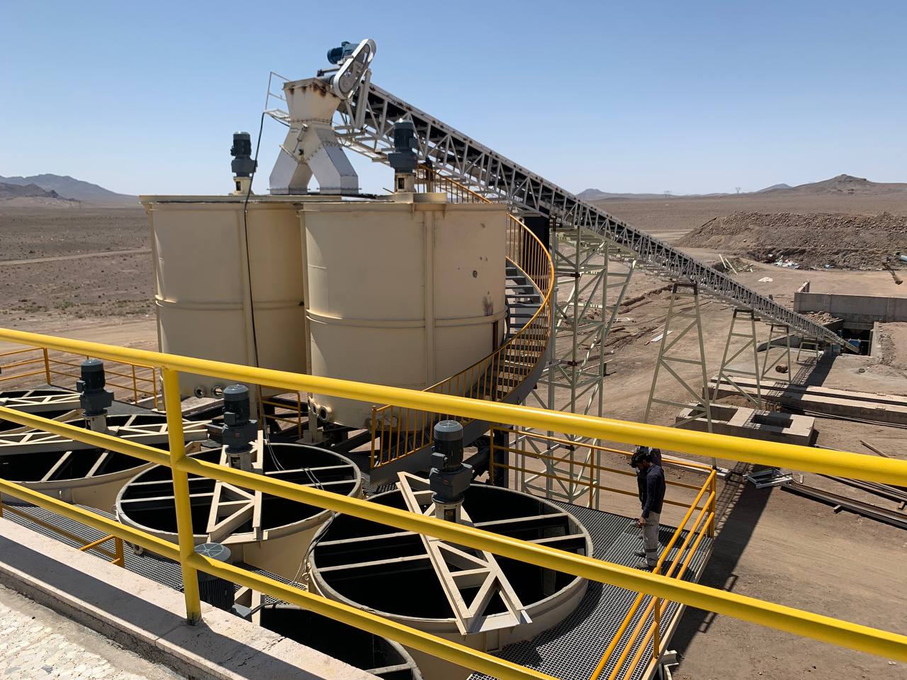
راهنمای جامع تولید مس: نگاهی گامبهگام به فرآیند استخراج، فرآوری و برآورد شاخصهای اقتصادی
سیلیکاژل در فرآیندهای فیلتراسیون صنعتی: مکانیسم تشکیل، روشهای پیشگیری و تکنیکهای رفع گرفتگی فیلترها
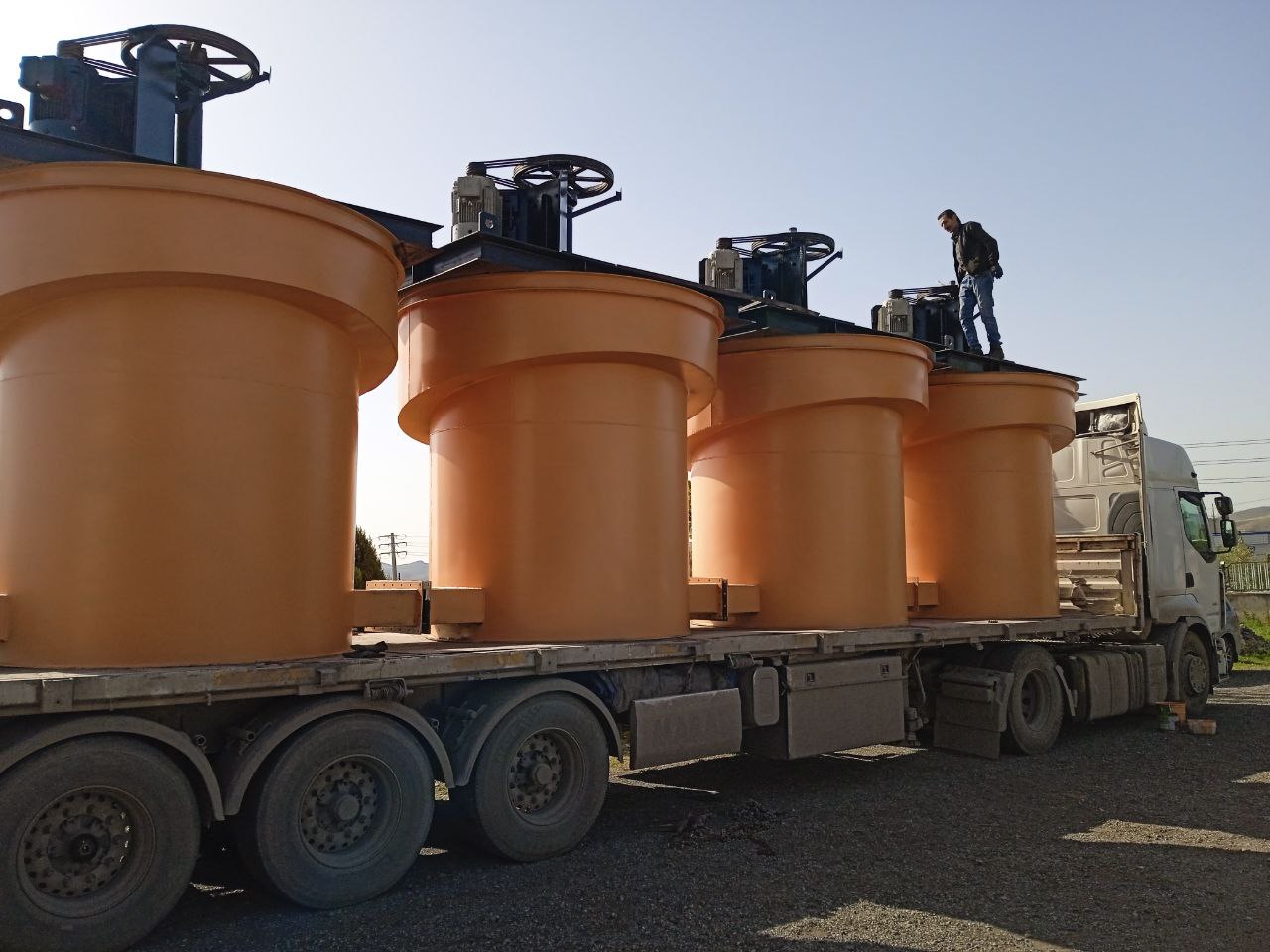
رازهای یک فلوتاسیون بینقص: همه چیز درون سلول اتفاق میافتد!
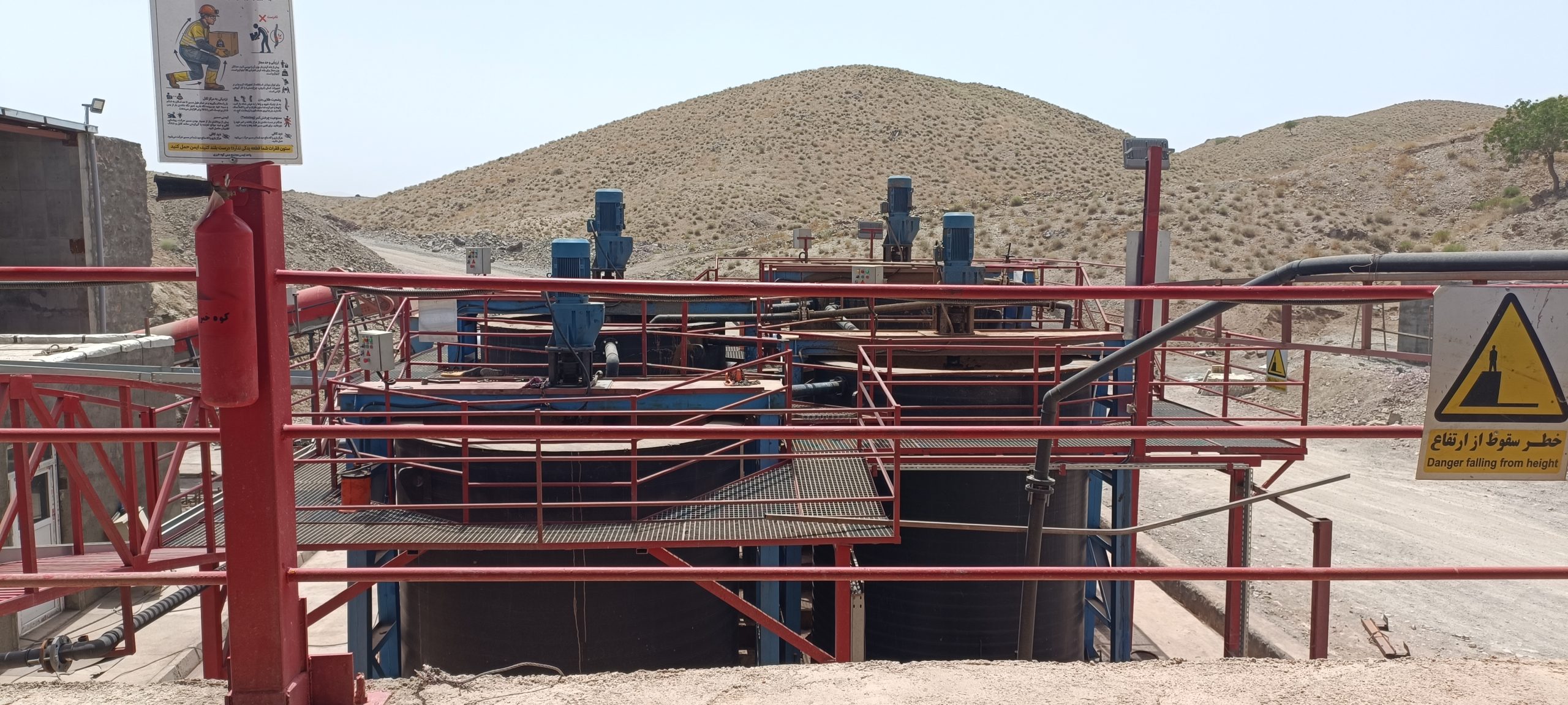
مشکل تهنشینی در تانکهای لیچینگ، ناکارآمدی همزنها و راهکارهای عملی بهبود عملکرد
۳ دلیل اصلی گرفتگی و پارگی کیسههای بگ فیلتر در معادن ایران + نقشه عملی عیبیابی
Azərbaycanın Dağ-Mədən Sənayesi üçün Yüksək Texnologiyalı Emal Həlləri: Taşko Mühəndislik Qrupunun Gücü
بگ فیلتر در کارخانههای فرآوری معادن: کنترل غبار، سود پنهان و حفظ محیط زیست
محاسبات کاربردی در راهاندازی خط فرآوری معادن فلزات: راهنمای جامع از طراحی تا بهرهبرداری
طراحی و ساخت تجهیزات فلوتاسیون، آبگیری و جداسازی طلا و مس | راهنمای جامع + مشخصات فنی و عوامل موثر بر هزینه
Ներդրումներ Հայաստանի Հանքարդյունաբերության Ոլորտում
تجهيزات كاملة لمعامل ومصانع العراق – من الهيدروسيکلون للكورة الدوارة وكل شي بينهم
۱۰ حقیقت شگفتانگیز درباره فرآوری طلا که تاکنون نمیدانستید
۷ مشکل رایج در مدارهای فلوتاسیون و روشهای عیبیابی آنها
انقلاب در لیچینگ مس اکسیدی: از فناوریهای نوین لیچینگ تا طراحی نسل آینده راکتورهای همزن (Stirred Tank Reactors)
هیدروسیکلون چیست؟ صفر تا صد طراحی، جنس، کاربرد و اشتباهات رایج در فرآوری مواد معدنی
راهنمای کامل طراحی و انتخاب سیستم انتقال مواد (Material Handling) در کارخانه فرآوری
راهاندازی خط فرآوری فلزات: از ایده تا تولید
تجهیزات ضروری برای احداث خط فرآوری طلا با نگاه بومی سازی
مقایسه سلولهای فلوتاسیون Sala و RCS در صنعت فرآوری مواد معدنی
ارزیابی ۴ فاکتور کلیدی در طراحی تجهیزات فرآوری برای افزایش بازدهی کارخانه
تأثیر فناوریهای نوین لیچینگ و فلوتاسیون بر طراحی نسل آینده راکتورها و سلولها
مهندسی و ساخت تجهیزات تحت فشار در صنایع معدنی: چالشها، استانداردها و فناوریهای نوین